Introduction
Skeletal anchorage provided by TAD’s has attracted great attention in recent years because of its versatility, low cost and minimal surgical invasiveness. The angle of insertion should be proper, this is important for cortical anchorage, patient safety, and biomechanical control. The use of a proper insertion angle reduces the risk of damaging the dental roots of adjacent teeth and also provides increased surface contact area between the micro-implant and the bone. But the actual impact of different insertion angulations on micro-implant stability is unknown.1
Mini-implants inserted at 60° to 70° to the bone surface have been shown to exhibit greater primary stability. There is a correlation of bone remodelling between bone/screw interface and the screw mobilization mechanisms with the structural response of the bony tissue to the TADs and then to the stress/strain field developing within the themselves and within the surrounding bone.2 The manner in which stresses are transferred to the surrounding bone determines the success or failure of mini implants.3 The risk of damaging the dental roots of adjacent teeth can be reduced by using a proper insertion angle and which in turns increases the surface contact area between the micro implant and the bone.4
Stress distribution along the surfaces of a mini implant and in the surrounding bone with different angulations of implant placement under retraction forces during enmasse retraction have been evaluated by previous studies. Jasmine IF and Vadivel KM, from their study concluded that stress on the mini implant and bone decreased as the insertion angle increased from 30°to 90°.4 Sivamurthy G et al, concluded that stresses in the mini implant and in the cortical bone increased on increasing the insertion angle from 30° to 60°, under the orthodontic retraction forces in both the maxilla and the mandible.3
Development of an effective model for analysing them is required since measurement of these stresses in vivo is virtually impossible. So, to analyse structural stress finite element method (FEM) technique used. This method uses the computer to solve large numbers of equations to calculate stress on the basis of the physical properties of structures being analysed.5
The purpose of this study is to evaluate stress level at the mini implant site, placed at 5 different insertion angles with relation to en-masse retraction force using a Finite element analysis.
Materials and Methods
Models were scanned with computed tomography with a slice thickness of 1.5 mm and maxillary first premolar was removed to stimulate extraction space. After scanning them with computed tomography at a slice thickness of 1.5 mm, the following components were generated as three-dimensional (3D) finite element models (FEM) in order to mimic the extraction space after the maxillary first premolar was removed from the model. Using the reverse engineering method, a geometric model (Figure 1) of brackets, tiny implants, archwire with crimpable hook, and nickel-titanium closed coil spring was created. The stainless steel MBT prescription with a slot size of 0.022 inch by 0.028 inch was utilized to manufacture the bracket models. A nickel-titanium closed coil spring with a retraction hook between the maxillary lateral incisor and canine was placed in 0.019 inch x 0.025 inch dimension Stainless steel archwire, and it is attached from a crimpable hook to the mini implant head to retract anterior teeth. The mini implants were placed at buccal alveolar surface with an angulation of 30, 45, 60, 90, and 120 degrees. 200 gms of retraction force was used. FEM models were created, with all parameters kept same with the exception of the mini implant's insertion angle, which are 30°, 45°, 60°, 90° and 120°.

Figure 2
FEM software ANSYS used for the study (model ofthe mini implant placed inside the bone block)


Bone blocks were modeled for the study in order to make the model simpler and cut down on processing time. The cortical and cancellous bones of the bone model (Figure 2) had a thicknesses of 1 mm and 10 mm, respectively.
The mini implants (Figure 3) were modeled with varying diameters (1.3mm, 1.6mm, and 2.3mm) and varying lengths (7mm, 8mm, 10mm). The implant insertion angulations used were 30°, 45°, 60°, 90°, 120°.The pitch of the implant thread used was 0.5mm. This was fixed in all implant designs in this study. The procedure of meshing was used to separate each model into a limited number of elements after it had been generated. Tetrahedral meshing was used to mesh the model. The entire geometry is made up of a collection of discrete parts called elements that are joined to form a finite number of nodes. In this study, the model used was tetrahedral and consisted of elements and nodes.
Properties of cortical bone, cancellous bone (D3) and implants are mentioned below.
Elements and nodal lists
Table 1
Elements and nodal lists
|
Model |
No of elements |
No of nodes |
|
Full model |
3355666 |
4484387 |
|
Cancellous bone |
2807707 |
3803393 |
|
Cortical bone |
466627 |
650236 |
|
Mini implant |
19499 |
30758 |
|
Total Number of Contact Element |
61833 |
|
All materials were thought to be elastic and transversely isotropic. Prior studies provided the mechanical characteristics (Poisson's ratio, Young's modulus).
Material parameter
Table 2
Material parameter
|
Materials |
Young’s Modulus |
Poisson’s Ratio |
|
Cancellous bone |
1600 MPa |
0.3 |
|
Cortical bone |
13,700 MPa |
0.3 |
|
Mini-Implant |
110000 MPa |
0.35 |
With 0 degree of mobility in all directions, boundary conditions were established at all of the bone's peripheral nodes. 200g of force was applied to the tiny implant's head to mimic the force needed to completely pull out six anterior teeth. To the ANSYS software version 17.0, all models were exported. This was followed by analysis of the Von Mises stresses in the cortical and cancellous bone and the mini implant in response to applied loads.
Results
According to results, von Mises stress had changed. After the material attributes were allocated, the color changes in terms of the areas of maximum and minimum stresses were seen. The maximum stress region is shown in red, and the minimal stress region is shown in blue. The following describes the pattern of stress distribution and the size of the stresses that took place in 9 different implants 200 gms of force were applied to the implants, which were placed into bone cubes at varying angles (30°, 45°, 60°, 90°, and 120°).
Using the above mentioned forces, stress and strain distribution pattern on the bone and on implants were studied using ANYSYS software.
In the cortical bone As it went away from the tiny implant and got close to the upper and small portion of the lower crest of the cortical bone, stresses consistently dropped as concentric circles.
In bone Von Mises stress was high in 1.3 × 8 mm implant at 60° angulation (fig 4). In Implant of 1.3 × 10 mm in 90° angulation showed high Von Mises stress (Figure 5). In Bone Von Mises stress was least in 2.3 × 7 mm implant at 30o angulation (Figure 6). In Implant of 2.3 × 8 mm in 30o angulation showed least Von Mises stress (Figure 7). Von mises stress generated on bone (Figure 8, Figure 9, Figure 10) and implants are shown in (Figure 11, Figure 12, Figure 13)
A. Stress generated on bone
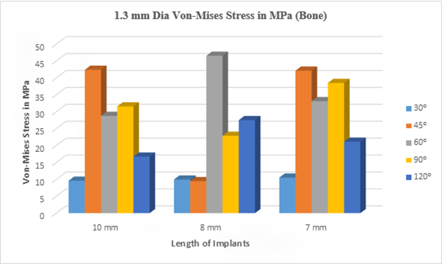
Graph 1
Bar diagram showing Stress on bone when 200gms of retraction force is applied using implants of 1.3 mm diameter and 3 different lengths at 3 different angulations.
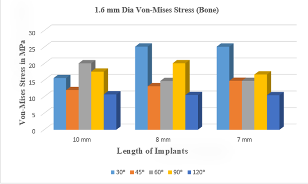
Graph 2
Bar diagram showing Stress on bone when 200 gms of retraction force is applied using implants of 1.6 mm diameter and 3 different lengths at 3 different angulations.
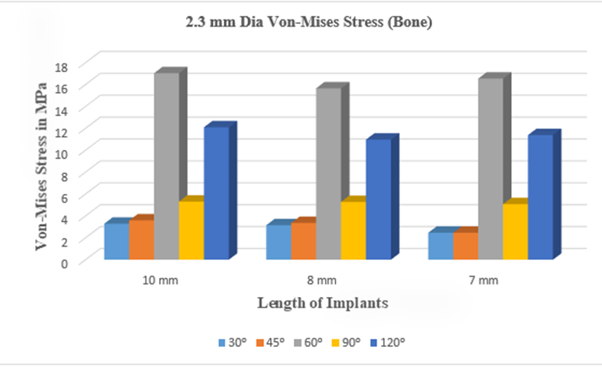
Graph 3
Bar diagram showing stress on bone when 200 gms of retraction force is applied using implants of 2.3 mm diameter and 3 different lengths at 3 different angulations
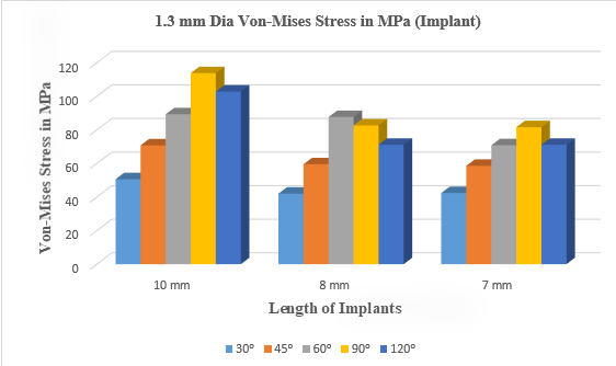
Graph 4
Bar diagram showing Stress on implants of 1.3 mm diameter and 3 different lengths when 200 gms of retraction force is applied at 3 different angulations.


Discussion
In the present study, it was observed that for a given load i.e, 200gms the stress values on surrounding Bone was highest at 46.505 MPA for 1.3×8mm with insertion angle of 450 followed by 42.361 MPA for 1.3×10mm with insertion angle of 45o and the least was observed at 42.087MPA for 1.3×7mm with insertion angle of 45°.
The stress values on Implant was highest at 113.81MPA for 1.3×10mm with insertion angle of 90° followed by 102.83 MPA for 1.3×10mm with insertion angle of 120° and the least was observed at 89.327MPA.for 1.3×10 mm with insertion angle of 45°.
The least stress on bone was recorded on implant size of 7 x 2.3mm with an insertion angle of 30° and implant size of 7 x 2.3 mm with insertion angle of 45°, the stress generated was 2.4611MPA. Second least stress on bone was seen in implant size of 2.3 x 8 mm with an insertion angle of 30o the stress generated was 3.1438MPA. The third least stress seen in implant size of 10 x 2.3 mm with an angulation of 30° the stress was 3.2912MPA.
When compared to other mini implants, the mini implant with the smaller diameter size showed higher stresses. The current study's findings agree with those of Chang et al.6, who found that tiny implants with greater threads, smaller tapers, and shorter taper lengths placed more stress on the bone and thread elements during lateral loading.
In their study, Gautham Sivamurthy et al.5 compared the maximum von Mises stress in the mini-implant and found that, no matter the length, the stress was concentrated at the neck and head of the mini-implant, producing stress levels that were significantly higher for mini-implants with a diameter of 1 mm. The comparison of stresses in the cortical bone revealed that the 1-mm diameter mini-implant generated high stresses. The stress also increased with increasing insertion angulation from 30° to 60°, with the stress being concentrated in the cortical bone around the threads of the mini implant.
When both intrusion and retraction are occurring at the same time, the 1.3 x 6 mm dimension mini-implants are advised to be used, and the 1.3 x 8 mm dimension mini-implant is advised to be used during molar intrusion.5 For less stress and greater stability, all of the mini-implants should be placed into the bone at a 30° angle. In the current study, placing the implant at a 30° angle and using a larger diameter resulted in less stress on the bone and implant.
In a finite element model, screws inserted at 90°to the alveolar process bone had significantly higher anchoring resistance than screws inserted at either 600 or 300. When loading screws are positioned at 90°, less cortical bone tension is produced than when they are positioned at 60° or 30°. The placement of temporary anchorage devices at angles less than 90° to the alveolar process bone surface does not provide advantages for force anchorage resistance, according to the study's findings. In the current study, when the diameter of the implant is greater (2.3mm), the stress is more visible at 60° angulation and less visible at 30° and 45° angulation.
While Lee et al.7 placed miniscrews at angles of less than 60°, their study showed a significant increase in maximum von Mises stress as a result of an increase in lateral force vectors compared to miniscrews placed perpendicular to the bone. This is in contrast to the present study, which found that implants with angles less than 60° showed minimum von mises stress.
Mini-implant biomechanical stability is increased by inserting them at a 90° angle to the bone surface, according to Jasmine et al. (2013).1 According to the study mentioned above, placing a mini implant at a less than 90° angle may result in longer lever arms, which would increase tension and displacement surrounding the mini implant. The threads of mini implants are not fully engaged in the bone when they are inserted obliquely or angulated, which causes a greater lever arm to form off the bone and reduces the primary stability. But as the insertion angle increased the stress levels with 1.3 x 10mm implant with a 90° inclination increased as well, and the reason may be a smaller mini implant's diameter.8
Based on a comparison of the maximum von Mises stress in the mini-implant, stress in the maxilla and mandible reduced as the insertion angle increased from 30° to 90°. According to a measurement of the maximum von Mises stress in cortical bone, both the maxilla and the mandible observed a decrease in stress when the insertion angle increased from 30° to 90°.9 Contrarily, the current study demonstrates that tension rises from 90° to 30°.
The stress values in the current investigation, however, were lower than the titanium's yield stress (692 Mpa)10, 11 showing that all mini-screws have the strength to withstand forces during orthodontic loading. The 1.3 x 8 mm implant at 60° angulation produced the greatest principle stress in the bone, whereas the 2.3 x 7 mm implant at 30° angulation caused the least principal stress.
With a 200 gms load and a 60° insertion angulation, the study's highest stress value of 46.505 MPa was observed. Given that this number is lower than the 133 MPa yield stress of cortical bone, it may be assumed that cortical bone won't undergo any appreciable negative alterations. As it went away from the mini implant and got close to the upper and small portion of the lower crest of the cortical bone, stresses decreased as concentric circles.11
Although real bone is neither homogeneous nor isotropic, the experimental models used in this study were considered to be linear, homogeneous, and isotropic. Instead of a jaw section, the geometry of the bone block was reduced to a rectangle block. The thickness of the soft tissue was planned, but it was not simulated.4
For en-masse retraction of maxillary anterior teeth using mini implant anchoring, optimal force values ranged from 200 to 250 g. Maximum stress was seen at the implant's head at the site of attachment with the retraction spring during en-masse retraction. Maximum stress in cortical and cancellous bone was observed distal to implant. Force levels in the 300 g range are undesirable because they could harm the PDL, the cancellous bone, and the teeth. As a result, they can withstand stress levels more than 300 g because the strains created on the implant and cortical bone under any load and angulation were relatively minimal compared to their yield strength.
The lowest maximum stresses under any load were created by the angulation of 60°, which was followed by 75°, and the least favorable angulation was 45°. The implant was inserted obliquely at a 60° angle, sufficient thickness of cortical bone was enveloped which provided primary stability and hence immediate loading can be done.4
In present study 90° angulated with less diameter showed high stress in implant and in 60° angulation with less diameter showed high stress in surrounding cortical bone.
Conclusion
Mini implant supported orthodontics was developed in response to the need for orthodontic treatment techniques that maximize anchoring control and reduce patient compliance requirements. As a skeletal anchorage, temporary anchorage devices (TADs) in the form of mini-implants have shown to be a reliable and acceptable method. The mechanical interlock between the bone and the mini implant provides short-term or primary stability of the mini implant, which depends on a number of parameters including bone quality, the location of the mini implant, the insertion angle, and the design of the mini-implants such as diameter, length, and pitch. With the application of en-mass retraction force on implants at five various insertion angles (30°, 45°, 60°, 90°and 120°) with different lengths and diameters, finite element method (FEM) was used to examine stress distribution at the mini-implants and in the surrounding cortical bone.
The present study derived the following conclusions
Mini implant which has got smaller diameter, long length and high inclination angle showed higher Von Mises stress when compared to other mini implants.
In implants Von Mises stress was high in 90° angulation of implant with long length.
In bone Von Mises stress was high in low diameter implant at 60° angulation
Implants with larger diameter showed less Von Mises stress
When the diameter was more the stress which produced was less in 30° and 45° angulation.
As the diameter and length increases the stress on implant decreases, it was more in 90° less in 30°.