Introduction
Facial esthetics is a major concern of many orthodontic patients. Unaesthetic facial profile with upper lip protrusion is commonly associated with protrusive bimaxillary dentition in Angle’s class I malocclusions,1 which leads patient to seek orthodontic treatment. In such cases major orthodontic goal is to reduce the proclination of maxillary incisors with treatment plan to extract bilateral maxillary premolars, followed by retraction of the anterior teeth with maximum anchorage.2
Louis Ottofy defined anchorage as “The base against which orthodontic force or reaction of orthodontic force is applied”. Recently Daskalogiannakis defined anchorage as “Resistance to unwanted tooth movement”.3
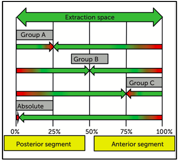
Gianelly and Goldman4 suggested terms maximum, moderate and minimum anchorage types, Marcotte5 and Burstone6 classified anchorage in 3 categories group A, B & C depending on how much of anchorage unit contributes to space closure. In Group A (maximum anchorage/critical anchorage) maximum space is used for anterior retraction with minimum movement of posterior segment (ratio 70:30); Group B (moderate anchorage) one half of the space be used for retraction (ratio 50:50); Group C (minimum anchorage) most of the space be closed by protraction of posterior teeth (ratio 30:70). Fourth type of anchorage has been added to Burstone's classification: Absolute anchorage. Clinically, it is very difficult to avoid movement in the passive unit; however, due to skeletal-based anchorage systems, significant steps have been taken towards achieving an absolute anchorage (Figure 1). 7, 8, 9, 10
Anchorage loss is seen during each stage of treatment but more so during space closure stage while retracting anterior teeth. En-masse movement follows two types of mechanics. Segmental or frictionless Mechanics in which anterior teeth are retracted with the help of a loop (eg. T-loop). For bodily tooth movement, the design of the loop/spring has to be accurate. Sliding or frictional mechanics, anterior teeth move together along the base wire under retraction forces applied by either an elastic chain or closed coil spring. This method puts lots of demand on anchorage. Heavier forces are employed to first overcome the friction between wire and bracket slot, and further cause tooth movement.
To achieve an optimum treatment result, anchorage control presumes utmost importance. The problems related to patient compliance in case of extraoral anchorage device, undesirable side effects on the maxillary complex and risk of injuries has limited its success. Orthodontic implants (temporary anchorage devices) enhance orthodontic anchorage, either by supporting the tooth of the reactive unit or by obviating the need of the reactive unit altogether.
The Finite Element Method (FEM), which is an Engineering Resource, introduced by Turner et. al in 1956 as one of the numerical analysis, has become an useful technique for stress and strain analysis in biological systems. The usage of computer softwares for the stressful calculations are used in order to find the stress and its distribution within a body for a given load for the displacement of the body before and after the application of load as well.11 In FEM the object to be studied is Graphically simulated on a computer, which defines geometry of the body being studied.
Materials and Methods
The present FEM analytic study was conducted in the department of Orthodontics and Dentofacial Orthopaedics, Swami Devi Dyal Hospital and Dental College (SDDHDC), Barwala, Distt. Panchkula (Haryana). Ethical clearance for the present study was obtained from institutional ethical committee of Swami Devi Dyal Dental College, Barwala, Haryana. The present study was conducted on 2 models of 23 year old patient having class I bimaxillary protrusion. The study material consisted of CBCT of a 23 year old patient who attended OPD of department of Orthodontics for fixed orthodontic treatment.
A maxillary geometric model was developed from 3D CBCT scan images obtained from data available in the institute using “Mimics software”. The complete geometry included an assemblage of discrete pieces called elements, that was connected at a finite number of points, called nodes. Model comprised of compact and cancellous bone of craniofacial skeleton. The geometric models of the maxillary dental arch except for the first premolars were constructed.12 Teeth inclination and angulation were arranged as described by Germane et al.13 and Andrews14 but curve of Spee and curve of Wilson were not made. (Figure 2).
The teeth and the bracket were connected without interference, and each tooth was independent and connected to the other by contact points.15 In order to establish the natural anatomy, periodontal ligaments (PDL) were constructed as a linear elastic film with an average thickness of 0.25mm around the roots of all the teeth. In the next step, alveolar bone was constructed. Then PDL and the teeth were fitted into the bone. Material parameters according to young’s modulus and poisson’s ratio were applied (Table 1).
Table 1
Material parameters
|
Material |
Young’s modulus |
Poisson’s ratio |
|
Tooth |
2.0 x 10⁴ |
0.30 |
|
PDL |
0.68 |
0.49 |
|
Alveolar Bone |
2.0 x 10³ |
0.30 |
|
Arch Wire/ Power Arm |
2.1 x 10⁵ |
0.30 |
|
Bracket/ Implant |
2.1 x 10⁵ |
0.30 |
Brackets with slot size of 0.022 x 0.028 MBT (ORMCO) were designed and given properties of stainless steel which were attached to the buccal surfaces of the teeth (4.5mm from incisal edge of the central incisor and canine, 4mm from incisal edge of the lateral incisor, 3.5 mm from the incisal edge of the premolar). Table shows properties of the materials used in this study.
A 0.019 x 0.025 inch (3M Unitek) stainless steel arch wire with anterior hook 7 mm long made from stainless steel wire (0.019 in x 0.025 in ss wire) was attached bilaterally to the arch wire between the lateral incisor and canine. The mini screw of size 1.2 x 9 mm was placed 9 mm above the cervical area at distal of the second premolar and mesial of the first molar for anchorage, Because of their stability in bone, fixed nodes were used as the mini screws.16, 17(Figure 3)
The calculation of the amount and direction of orthodontic tooth movement are based on the resorption and apposition of the alveolar bone (bone remodelling). Anchor loss is measured by the amount of displacement of posterior segment mesially. Retraction of anteriors is measured by the amount of displacement of anterior segment distally. Anterior enmasse retraction was accomplished with application of forces from the mini screw in buccal location and T-loop placed in archwire bilaterally in maxillary arch. Continuous T-loop made from TMA 0.017 x 0.025 inch wire as per Busrtone was engaged in the brackets including second molar tubes in posterior segment which served as conventional anchorage unit.
Anterior enmasse retraction
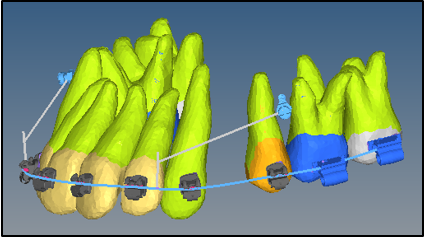
Anterior en-masse retraction was accomplished with application of forces from the mini implant to power arm with an e chain buccally and T loop placed in archwire slots bilaterally in maxillary arch.
T- loop arrangement
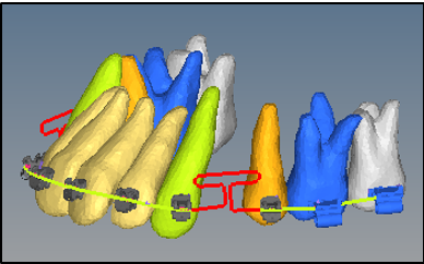
Prefabricated 0.017 x 0.025 inch TMA, T-loop (ORMCO Corp) archwire in standard form as described by burstone was used with design based on the T-loop for symmetric space closure. Centric positioned T-loop around extraction spaces was activated by cinching the archwire distal to second molars providing force vectors of 150 gm/side for enmasse retraction.(Figure 4)
Mini implant arrangement
Mini implants were placed on both sides of maxilla. Power arm or the crimpable hooks of 7 mm length were placed in anterior segment distal to lateral incisors. Pre stretched e chain was applied from mini implant to power arm engaged in anterior segment distal to lateral incisor bilaterally which generated force vectors of 100gm/side for enmasse retraction (Figure 5).
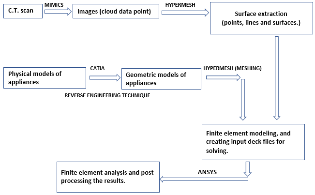
Conversion of geometric model to finite element model
Geometric model was converted into finite element model with finite number of elements and nodes. (Figure 6 and Table 2)
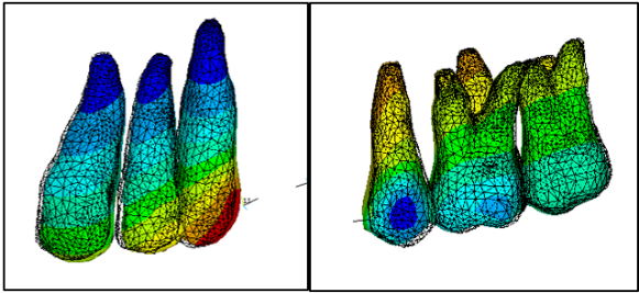
Table 2
Number of nodes
|
Structure |
Node number |
|
Bone |
1,51,000 |
|
Pdl |
6,500 |
|
Teeth |
2,00,000 |
|
Hook |
500 to 1600 |
|
Bracket |
12,000 |
|
Wire |
1,100 |
|
Total |
3,71,000 |
FEM makes it possible to analytically apply various force systems at any point and in any direction and also quantitatively assess the distribution of such forces through the wire and related structures.18 Methodology flowchart as given below.
Results
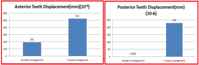
Anterior teeth displacement (mm)
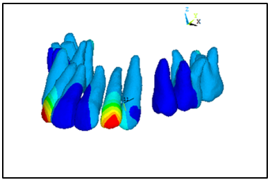
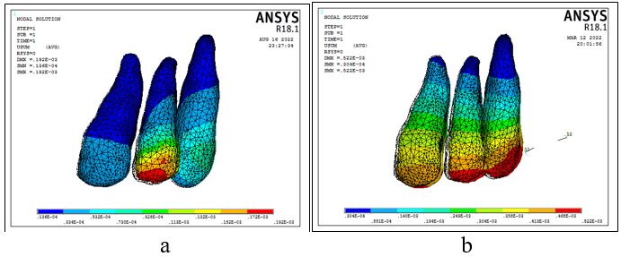
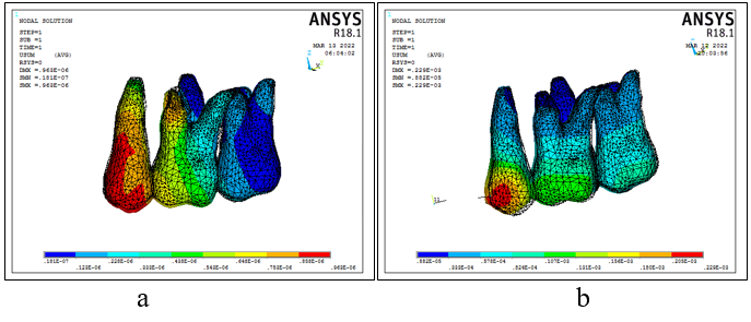
In implant arrangement maximum displacement of 192 x 10-6 mm was seen in anterior teeth with maximum stress seen around lateral incisor (Figure 8 a & b).
In T- loop arrangement Maximum displacement of 522 x10-6 mm was seen in anterior teeth with maximum stress around canine. More stresses around the incisal edges of canine and lateral incisor suggest tipping movement initially under T-loop arrangement when en masse retraction commences (Figure 8 a & b).
Posterior teeth displacement (mm)
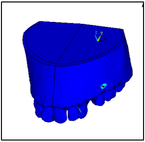
In implant arrangement maximum displacement of 0.963 x 10⁻⁶ mm was seen where maximum stress was seen around second premolar followed by mesio buccal root of max first molar because of implant placed around that region (Figure 9 a & b).
In T-loop arrangement maximum displacement of 229 x 10-6 mm was seen where maximum stress was seen around second premolar followed by coronal parts of first molar (Figure 9 a & b).
Discussion
Anchorage is a critical component of en-masse retraction. The boundaries of orthodontic treatment have been redefined With the advent of skeletal anchorage, using dental implants, 19 miniplates, 20 miniscrews,20 and micro screws.21, 22 Use of implant provide an absolute anchorage for tooth movements. The implants were placed as per guidelines of Park 23 in upper arch between the first molars and second premolars, as in maximum retraction cases, Upper molars provide less anchorage than lower molars.24
Few studies have measured the anchorage loss with implant assisted en-masse retraction.25 Hence, the present study was aimed at evaluating maximum retraction of anterior teeth (bimaxillary protrusion) and anchorage loss in patients requiring extraction of all four first premolars with implants made up of surgical steel and with conventional methods of anchorage reinforcement using Finite Element Analysis.
FEM is an engineering resource used to calculate stress and deformations in complex structures, and it has been widely applied in biomedical research.26 The FEM principle is based on the division of a complex structure into smaller sections called elements27 with physical properties, such as the modulus of elasticity which are applied to shape and analyse any material or dentomaxillafacial structures.28 Such experiments require the use of living animals in laboratory and ethical committees on animal research have objections. Using humans or animals for such experiments or studies can have various deleterious effects for eg. unnecesaary tooth movements, extra force applications can cause bone and tissue loss, effects of treatment not achieved. Patient compliance will also be a problem, which in this case is eliminated. Alternate experimental models used to analyze the biomechanics of tooth movement include photoelastic models; 29 with disadvantage of exploring only the surface of the model, leaving internal structures, such as the periodontal ligament, behind. FEM has reformed biomechanical research in Orthodontics as non-invasive and accurate method to provide quantitative and detailed data regarding the physiological responses occurring in tissues, such as the periodontal ligament and the alveolar bone.
In the present study, a sample of 2 models of same patient with class I bimaxillary protrusion requiring extraction of all first premolars were assigned which were fabricated with FEM. In Implant arrangement mini implant was used for sliding enmasse retraction of maxillary anterior teeth and T loop arrangement for en-masse retraction and second molar was used for anchorage reinforcement in.
Results in our study showed the anterior teeth movement (en-masse retraction) as anterior teeth displacement. This showed the displacement of anterior teeth to be higher in case of T-loop arrangement than the implant arrangement. This study showed anchorage loss as posterior teeth displacement which was seen in posterior teeth where maximum stress was seen around cervical region of second premolar in implant arrangement followed by mesio buccal root of max first molar because of implant placed around that region.
This study is similar to that of Sharma et al.30 in which a comparison was made between mini-implants and TPAs as anchorage devices in relation to dental movements following retraction. However, their RCT included an evaluation of only canine retraction, whereas the complete picture of the whole upper anterior teeth retraction is presented in this paper. They found no movement of molars in the mini-implants group and a mean of 2.48 ± 0.71 mm mesial movement in the TPA group, this study also showed no mesial movement of molars in implant the anchorage loss to be greater in T-loop arrangement than implant arrangement.
Contrary to previous reports, we found no significant shortening of treatment time in patients treated with implants.31 There are two possible explanations for this: In implant arrangement, space closure was performed only by distalization of anterior teeth. In the T-loop arrangement retraction mechanics there was anchorage loss, so simultaneous movement of anterior and posterior segments happened shortening the time for space closure. Treatment time depends not only on the rate of tooth movement but also on other variables such as mechanics, patient cooperation and patient motivation.
The second reason that we observed was that in both groups retraction was carried out on 0.019 x 0.025 in stainless steel wire; whereas in a previous study, by Park HS 32 the retraction was carried out on 0.016 x 0.022 in stainless steel wire in 0.022 slot. Because the anterior inclination was dictated by the control of force direction, the torquing curve on the archwire and retraction of six anterior teeth with sliding mechanics, the need for heavy archwire decreased. Heavy archwire are known to produce more friction than lighter archwires. Therefore, 0.016 x 0.022 in archwire in 0.022 in bracket system produced less friction than 0.019 x 0.022 in archwire and hence facilitated faster tooth movement.
The results of this study conflict with the suggestions made by several authors Aljhani A et. Al 33, Becker K et al. 34 and Upadhyay M et. al.16 who advise placing orthodontic miniscrews for more displacement and faster retraction. However, based on the results of this study and those of previous studies a mini implant placement is recommended as long as anchorage loss needs to be minimized.
The amount of retraction of upper anterior teeth as demonstrated by displacement of anterior teeth was greater in T loop arrangement. These results did not match with those of Lai et al.,1 Upadhyay et al.16, Liu et al. 35, Kuroda et al. 36 Park et al. 37 Lee et al. 38, and Sibaie and Hajeer 39 who reported more distal movement of upper incisors in mini-implant group (6.9mm- 6.23mm- 8.17mm- 7.03mm- 9.3mm- 6.9mm- 6.87 mm- 5.92 mm) respectively than those of conventional anchorage group (5.5mm- 5.72mm- 6.73mm- 4.76mm- 6.3mm- 5.3mm- 4.5mm- 4.79mm) respectively. On the other hand, this study contradicted results of Feldmann and Bondemark40 also found no significant difference between the implant group and conventional anchorage group in terms of incisor retraction. Whereas in this study implants were proven to show lesser displacement for the same time of application of force.
Whereas, studies by Yao CC et al.1, Kim SH et al. 2 Kuroda S et al.36 Chung KR et al.41 Park HS et al.42 reported a mesial movement of the upper molars despite the use of mini-implants as an anchorage tool. This may be due to the use of retraction utility archwires directly supported by mini-implants without engaging the upper molars in active treatment,18 the physiological mesial movement that occurred after early extraction of the upper first premolars at the beginning of the treatment with a delayed initiation of the retraction process, difference in the retraction mechanics.
The conventional anchorage mechanics used in this study did not significantly enhance orthodontic anchorage. This goes in line with the concept that, in the treatment of premolar extraction patients with traditional mechanics, the maxillary molars were usually mesialized approximately 30% into the extraction space.33, 43 When evaluating the efficacy of miniscrew and conventional anchorage during en-masse retraction of anterior teeth, the results of the study showed that implant arrangement had lesser displacement and lesser stresses in anterior zone whereas T loop had higher amount of anterior teeth displacement and higher stresses in bone around anterior zone. This was due to more amount of forces applied by the T loop and the direction of forces applied. In case of implant, vector factor is applied for force application so net amount of force applied for bodily movement is lesser whereas the forces in case of T-loop are purely horizontal and are applied while teeth being in direct contact creating higher displacement.
Conclusions
Time taken for retraction by mini implant arrangement is more than the T-loop arrangement
The mini-implants placed in the inter dental bone between the maxillary first molar and second premolar proved to be efficient for intraoral anchorage reinforcements for enmasse retraction.
Mini implants placed in the maxillary arch provided absolute anchorage for enmasse retraction of anterior teeth.
Maxillary incisors were retracted more in the conventional than in mini implant anchorage groups when force was applied for the same duration.
Less anchorage loss in the implant arrangement but significant anchorage loss was seen in T-loop wire in maxillary arch.